

 Order Status & Returns
 Gift Cards
 Help Center
 1-800-345-4545
 Vehicle Info Needed
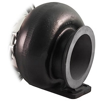
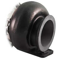
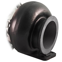
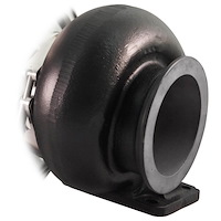
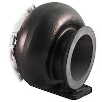
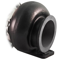
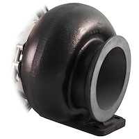
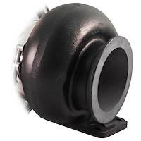
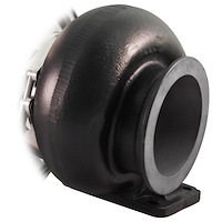
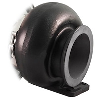
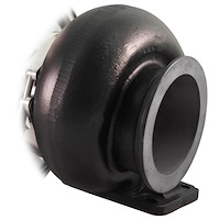
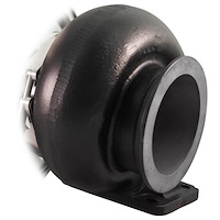
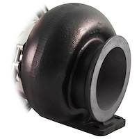
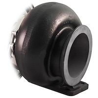
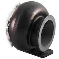
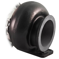
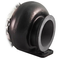
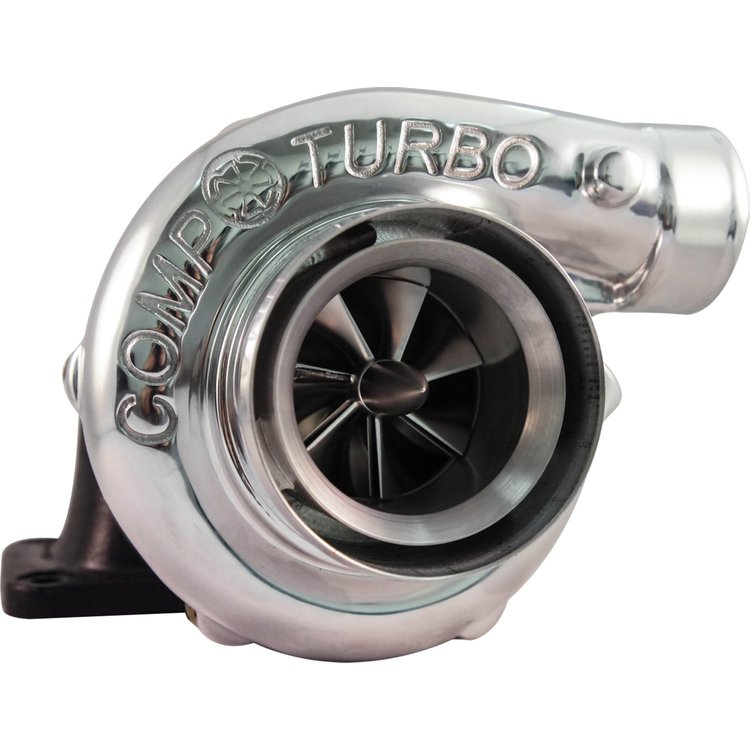
CT4X Turbo 70 75 Oil-Less 2.0
 Ships on 10/09/2026
 Lowest Price Guarantee
NOTE: DOES NOT INCLUDE TURBINE (HOT) SIDE HOUSING.
TRIPLEX CERAMIC Oil-Less Turbocharger Technology
Comp Turbo Technology Inc, continues to extend the boundaries of turbocharger technology by announcing the availability of what is believed to be the first commercial automotive turbocharger that does not require a lubricating oil supply from the engine. Lube oil supply and drain lines are no longer necessary and the Comp Turbo oil-less turbocharger can be mounted in a variety of positions and locations that were not possible when lube oil had to be gravity drained back into the engine crank case.
Historically, lube oil has been the source of a number of problems throughout the development of the small automotive turbocharger. The thick viscosity of lube oil in cold weather causes a significant time lag before oil reaches the turbocharger bearings. Repeated hot shutdowns of an engine can cause a buildup of hard carbon within the turbocharger's bearing housing. In addition, the piston ring oil seals used in commercial turbochargers have a small leak path that has caused a minor but persistent problem up to and including some current models. All these annoyances have been eliminated by removing the use of lube oil in the Comp Turbo oil-less turbocharger.
Designated the Model CT3B-OL, it employs the well proven, patented TRIPLEX CERAMIC bearing system with high temperature grease lubrication. Replacing lube oil with grease results in a lower friction loss in the bearing system allowing somewhat faster acceleration of the turbocharger rotor, which is quite advantageous in racing applications. Since the ball bearing carrier in the new oil-less turbo can be easily removed from the bearing housing as an assembly, the bearings can be re-greased at appropriate intervals, thereby extending their service life indefinitely.
TRIPLEX CERAMIC Oil-Less Turbocharger Technology
A great deal of effort was expended in the early years of small turbocharger development to produce a bearing system that had sufficient durability to make them commercially viable. Research and development in the 1960's resulted in the perfection of shaft instability (oil-whirl) but had appreciable friction losses at their high speeds of operation.
Due to the friction losses in the floating sleeve systems that hamper the acceleration rate of the turbocharger rotating assembly, many attempts were made to use ball bearings in small turbochargers, all unsuccessful, until the TRIPLEX CERAMIC ball bearing system was invented. This system consists of an elongated, rotatable steel cylinder with back-to-back angular contact ball bearings, mounted in the compressor end of the cylinder, that carry axial thrust in both directions, and a single angular contact bearing slidably mounted in the turbine end that carries no thrust. The turbine end bearing outer race bears against a preload spring that allows the bearing to move with axial expansion of the shaft. A small clearance between the outside diameter of the steel cylinder and the mounting bore in the bearing housing is supplied with the lube oil that protects the bearings from shock and vibration. This triple ball bearing system has been successfully used in commercial production by Comp Turbo Technology for over three years, has out-performed competition in stringent racing applications and has produced a large number of very satisfied customers.
Historically, the use of engine oil to lubricate the floating sleeve and stationary thrust bearings in commercial turbochargers have rise to a number of operational problems. To prevent oil leakage into the compressor and turbine casings, piston ring seals are employed in commercial turbochargers. Since the piston ring seals are not positive contact seals, there is a small leak path around the piston rings and, during certain operating conditions of the engine, i.e. low idle or a vacuum in the air intake system, some oil leakage can occur. Any ail leakage into the turbocharger casings can result in the undesirable emissions in the engine exhaust.
In cold weather, there can be a significant lag in the flow of oil to the turbocharger bearings when the engine is initially started. If the lag is long, the sleeve bearings can fail on startup.
Another problem can occur when an engine is shut down quickly after being operated at high speed and load where the exhaust gas temperature is maximized. Heat transferred into the turbocharger casings can cause residual lube oil in the bearing system to carbonize. This carbonization can build up and eventually cause failure of the bearings.
Notwithstanding the fact that years of development has mitigated the above named problems, there remained a motivation to remove the use of engine oil to lubricate the bearing systems in small turbochargers. Comp Turbo Technology has responded to this challenge by developing what is believed to be the first commercial turbocharger that does not require a lubricating oil supply from the engine. Lube oil supply and drain lines are no longer necessary and the turbocharger can be mounted in a variety of positions that were not possible when lube oil had to be gravity drained back to the engine crank case.
The Comp Turbo Technology oil-less turbocharger, employs the well proven TRIPLEX CERAMIC ball bearing system, wherein the ball bearings are lubricated by high temperature grease. In the oil-less bearing system, the elongated steel cylinder is provided with axially spaces “O” rings in its outside diameter that engage the bore in the bearing housing. Cooling water is supplied from the engine to a water jacket in the bearing housing and to the space between the “O” rings. This cools the “O” rings and the bearing carrier, carrying away the heat generated in the bearings. Since the bearing system is easily removed as an assembly from the bearing housing, the bearings can be re-greased at appropriate intervals to extend their service life indefinitely.
The turbochargers manufactured and sold by Comp Turbo, embody the latest in small turbocharger design technology. The three main components that contribute to the turbocharger overall efficiency and it's performance on the engine are the compressor, bearing system and the turbine.
Compressor Design
Referring now to the compressor component, a primary design objective is to obtain the most mass flow through small diameter wheels, thereby minimizing the inertia of the rotating assembly. The mass flow through the compressor wheel is controlled by the net axial flow area at the inducer inlet. Cutting back alternate inducer vanes opens up the flow area at the base of the vanes and allows the hub diameter to be minimized. Obviously, a large inducer vane outside diameter, along with the small hub, maximizes the net inlet axial flow area. Usually, several inducer vane outside diameters are employed to produce several different flow ranges from a single wheel casting. The inducer vanes are made as sharp as possible along their entrance edges to minimize entrance losses and this contributes to maximizing the net inlet flow area and the flow range of the compressor.
It is usual to limit the inducer vane outside diameter to about 75% of the wheel O.D. to limit the stress at the base of the vanes. Exceeding the 75% limit can increase the vane base stress to values that can exceed the material properties of cast wheels and force the wheel to be machined from a billet. This is an unnecessary expense since 75% inducer wheels made from economical casting material have adequate flow range for essentially all commercial applications. There is no reason to use a full bladed inducer. The evolution of small compressor performance took a giant step forward with the development of wheels that employ alternately cut back inducer vanes.
It is desirable to select a relatively large number of compressor wheel vanes to maximize the pressure ratio capability of a given size wheel. The exit velocity of the compressed air can never reach the exit velocity of the vanes, and this difference is termed wheel "slip". To illustrate this phenomenon, an approximation of wheel slip can be calculated by using the Stodola equation from the literature:
Wheel slip = 1 – ?/N where N is the number of vanes.
A 14-vane wheel would have a slip factor of 1 – ?/14 = .776.
An 11-vane wheel slip factor would be 1 – ?/11 = .714.
This comparison indicates that the 14-vane wheel will have a significantly higher pressure ratio capability than an 11-vane wheel because of its greater air exit velocity. The even vane number of the 14-vane wheel allows the wheel to have all the advantages of alternate cut back vanes. A wheel with 11 full vanes could always have its flow range and pressure capability increased by adding a vane and alternately cutting back the inducer vanes.
The airflow conditions at the wheel outside diameter are very important for achieving high efficiency and broad range. A typical velocity triangle representing wheel exit parameters is given below.
CU2 = U2 (1 – ?/N)
U2 = tip velocity
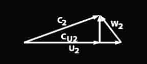
Due to "slip",the tangential component of the air exit velocity is less than the wheel speed and the relative velocity, W2, dictates the design of a backward curve in the vanes to match the relative exit velocity so that the vane wake loss is minimized. Designing back sweep into the vanes as they near the exit or O.D. improves both the efficiency and the flow range of the compressor.
Consideration of all the foregoing design factors results in the availability of broad range compressors with maximum efficiencies approaching 80%, while still retaining relatively small size to minimize rotational inertia.
Referring to the compressor casing, a re-circulation slot can be designed into the casing located just inboard of the inducer inlet. This feature can produce a lower surge line and broaden the flow range of the compressor at high pressure ratio. The re-circulation slot is an outgrowth of work done at NASA, where the flow range of axial flow compressors was enhanced by several types of tip treatment. The re-circulation slot has been a useful addition to small compressor design technology.
Bearing System Design
Referring now to the turbocharger bearing system, Comp Turbo turbochargers utilize the latest in high-speed ball bearing technology. The acceleration rate of a turbocharger is a function of the rotor inertia and the friction losses in the bearing system. Conventional commercial turbochargers use floating sleeve bearing systems that are a result of years of experimental development. The floating sleeve bearings have an inner and outer oil film fed by lube oil under pressure from the engine’s lubricating oil system. They must also employ a separate stationary thrust bearing that is fed lube oil under pressure from the engine. The friction loss attributed to a stationary thrust bearing is proportional to the fourth power of the radius and can amount to several horsepower at the high speed at which turbochargers operate.
The oil films in conventional floating sleeve bearings have significant viscosity that produces appreciable friction losses due to oil film shear when the turbocharger rotor is accelerated and running at high speed. The friction losses in the sleeve bearing systems and in the stationary thrust bearings result in mechanical efficiencies in the middle 90% range in conventional turbochargers.
The Comp Turbo turbochargers use a ball bearing system that does not need a separate thrust bearing since the ball bearings carry both the radial load and the axial thrust loads. There is little or no oil film shear in ball bearings that operate with rolling friction only so that Comp Turbo turbochargers accelerate much faster than conventional turbochargers that use sleeve bearing systems. The Comp Turbo bearing system is a proprietary design that is unique in the industry. It utilizes full compliment angular contact ball bearings with ceramic balls. Compared with steel balls, ceramic balls in ball bearing have a number of advantages.
According to a prominent ball bearing manufacturer, bearing service life is two to five times longer than steel balls, they run at lower operating temperatures and allow running speeds to be as much as 50% higher. Also, since the surface finish of ceramic balls is almost perfectly smooth, they have lower friction losses and lower vibration levels. And, since there is less heat buildup during high-speed operation, they exhibit reduced ball skidding and have a longer fatigue life.
All these characteristics make ceramic ball bearings ideal for use in turbochargers where they must operate at very high speeds and survive in a high temperature environment. The full compliment bearings do not use a cage to position the balls and this additional feature, combined with the ceramic material, provides a combination that has minimal friction losses. The mechanical efficiency of Comp Turbo turbochargers that use ceramic ball bearings can approach the high 90% range and this contributes to rotor acceleration rates that have been shown to be faster than competition.
In the proprietary Comp Turbo ball bearing system, the angular contact bearings are mounted in an elongated steel cylinder that is free to rotate in the bearing housing. The outside diameter of the cylinder is fed with lube oil and this outer oil film provides a cushion against shock and vibration. Two angular contact bearings are mounted in tandem on the compressor end of the cylinder in an arrangement that carries rotor thrust in both axial directions. A single angular contact bearing is mounted under pre-load on the turbine end of the cylinder and is free to move axially with shaft elongation when heat is conducted down the shaft from the hot turbine wheel. The elongated steel cylinder containing the angular contact bearings represents the complete bearing system and can be inserted and/or removed as an assembly, making the Comp Turbo turbocharger fully serviceable and rebuildable.
Turbine Design
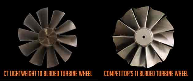
The Comp Turbo turbine wheels are a unique design in that they have vanes that are constant in outside diameter from inlet to exit. This design feature maximizes the flow capacity of a given size wheel and allows the use of reasonably small turbine wheels on large-size engines. One of the largest losses in small turbine wheel design is the leaving gas velocity, which is unrecoverable energy and is dissipated in the atmosphere when the exhaust gas leaves the turbine casing. The Comp Turbo full-bladed turbine wheels have minimal leaving velocity due to the large exit area, thus their leaving losses are minimized, leading to higher turbine efficiency and greater flow range than contoured turbine wheels. Conventional twin flow and undivided turbine casings are available to match different engine exhaust manifold systems.
Features:
- TRIPLEX CERAMIC ball bearings
- Oil-less 2.0
- Lightweight high efficiency 10 bladed turbine wheels
- Lightweight aluminum bearing housing
- Horsepower 500-1050
- Displacement 1.5L-6.0L Engines
- Interchangeable to a GT4088R models
Racing applications require turbochargers that build boost pressure as rapidly as possible, thus allowing the engine to develop high torque at low engine speed and with boost capability that can produce very high maximum power output. Comp Turbo turbochargers do exactly that. For example, when mounted on a drag race engine, the Comp Turbo turbocharger produced 1.7 bar boost in two tenths of a second and developed 650HP at full staged. Now, that’s phenomenal response and very impressive.
In street applications, the acceleration rate of a vehicle equipped with a Comp Turbo turbocharger is enhanced and moves the engine out of inefficient operating regimes more rapidly. An improvement in number of gallons of fuel used is the usual result when a vehicle is accelerated faster. Under steady-state operation, the lower HP losses in the Comp Turbo turbocharger ball bearing system means more power is available to the turbocharger compressor, which results in higher intake manifold pressure. In most cases, higher boost pressure can make an additional contribution to improving engine fuel consumption.
Comp Turbo supplies turbochargers with various compressor and turbine wheel trims to tailor their performance to exactly match specific engine application requirements, whether they be racing, street, off-highway, or stationary.
Intended Applications:
- Horsepower 400-1050 (hp range varies by turbo size)
- Displacement 1.5L-6.0L Engines
360 Journal Bearing
- Utilizes a 360 lubricated thrust bearing
- Entry level
- Billet compressor wheel
- Anti-surge compressor housing on selected models
- Fully rebuildable and upgradable
- Complete aluminum center section
- High speed ceramic ball bearings
- Rapid acceleration
- 3x the trust load capacity over journal bearing systems
- Up to 99% mechanical efficiency
- Water Cooled
- Uses high temperature grease to lubricate bearings
- Patented triplex oil-less ceramic system
- Can be mounted horizontal or vertical
- Compatible for Rear Mount Setup
- Does not Require Scavenge pumps or Oil-Lines
- Fully serviceable on site via zerk fitting located in the center of the bearing housing
NOTE: AS-CAST FINISH COMPRESSOR HOUSING AND TURBO DOES NOT INCLUDE TURBINE (HOT) SIDE HOUSING.
Items You Need