Sign up now to join the JEGS email newsletter and be the first to learn about new products, special deals and e-mail only offers!

 4 People Found This Article Helpful


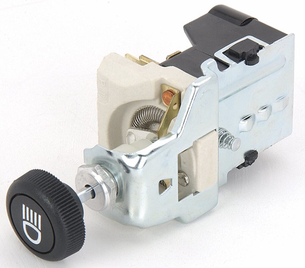
Upgrading or replacing a headlight switch in a GM vehicle requires a basic understanding of how the switch is wired and what each terminal controls. Whether you're restoring a classic muscle car or updating a hot rod project, correctly wiring your headlight switch ensures safe and reliable lighting. In this comprehensive guide, we’ll walk you through the wiring diagrams, functions, and installation steps for JEGS GM-style headlight switches, including both dimmer and non-dimmer options.
This guide also includes a helpful reference for anyone searching for a GM headlight switch wiring diagram, a 1970 GM headlight switch wiring diagram, or a downloadable GM headlight switch wiring diagram PDF.
GM-style headlight switches are commonly used in a wide range of classic cars, trucks, and street rods. These switches control multiple lighting circuits including the headlights, parking lights, tail lights, dash lights, and dome or courtesy lights.
There are two main types of GM-style headlight switches available from JEGS:


⚠️ Important Safety Note: Always disconnect the vehicle battery before working with the electrical system. Use inline fuses for all circuits to protect your wiring and components.
Here is a clear visual breakdown of a typical GM headlight switch with numbered terminals:

Each terminal serves a specific function. Refer to this chart for wiring reference:
| Wire # | Description |
|---|---|
| 1 | Battery input from fuse block |
| 2 | Wire going to dash lights |
| 3 | Wire going to dimmer switch |
| 4 | Wire going to park lights |
| 5 | Wire going to tail lights |
| 6 | Dome and interior light ground |
Note that on some switches, wire terminal #4 may be omitted. In these cases, the parking light output will be moved to the terminal next to #5.
Another wiring configuration, such as the universal 5-terminal switch, will not include connections for dimmer or dome lighting, simplifying the setup for certain applications like off-road or race vehicles.
Sign up now to join the JEGS email newsletter and be the first to learn about new products, special deals and e-mail only offers!
Use the included terminals or create a wiring pigtail. Wire according to the labeled diagram and chart above. The dome light ground is activated when the switch is turned fully to the left.
This version is ideal for LED dash light conversions or any system where dimming is not needed. With a 3-position OFF-ON-ON switch, connect your battery input, headlights, tail lights, and parking lights to the appropriate terminals using ring-style crimp connectors. Refer to the image below:

Incorrect wiring or poor connections can cause a range of problems. Here are common symptoms and how to resolve them:
No Headlights
No Dash Lights
No Dome Light
No Tail or Parking Lights
Pro Tip: Always test your lighting circuits with a multimeter before finalizing installation. This can prevent short circuits and ensure correct function.

Correctly wiring a GM headlight switch not only improves lighting reliability but also ensures compliance with vehicle safety standards. Whether you're installing the JEGS 555-11110 with dimmer and dome light features or the streamlined JEGS 555-11140, proper wiring is key.
If you're searching for a downloadable GM headlight switch wiring diagram PDF, simply save or print the diagrams and chart shown in this article. These visuals are compatible with most classic GM setups, including 1970 GM headlight switch wiring diagrams.
For high-quality headlight switches, wiring accessories, and tech support, trust JEGS. Our expert team is ready to help with your next electrical project. Visit JEGS.com for all your lighting and electrical needs.


Sorry to keep bothering you but I’ve still got problems with my wiring in my 1977 gmc truck. I took the steering column down and the white wire was pinched but not broken. As soon as I plug in my steering column wire is when my brake lights come on and as soon as I push the brake light switch they go off. Is there a special ground wire that I didn’t get hooked back up when I changed the cab. Anything you can suggest I would sure appreciate it. Thanks again. I also have no taillights either but everything else seems to be working

Linnie, you’re not bothering anybody, and honestly your latest update points much more clearly to the problem area. Since the brake lights come on when the steering column wire is plugged in, then go off when you press the brake pedal, the issue is very likely inside the turn signal switch wiring in the column or a grounding problem related to the rear lighting circuit.
That broken white wire absolutely could be part of the issue depending on what circuit it belongs to. On many GM columns, the turn signal switch routes the brake light power through the column before sending it to the rear lights. If a wire is pinched, shorted, or grounded inside the column, it can backfeed power and cause exactly the strange behavior you’re seeing.
The fact that you also have no taillights makes me strongly suggest checking the rear body grounds first. Since you changed the cab, there is a very good chance a ground strap or rear lighting ground was left disconnected. On those trucks, the cab, frame, bed, and rear light housings all need solid grounds to each other. A missing ground can cause the brake and turn circuits to try grounding through another filament, which creates all kinds of backwards electrical behavior.
Here’s where I would focus:
Repair the broken white wire correctly before further testing
Verify the steering column connector pins are fully seated and not shifted
Check for a cab-to-frame ground strap
Check rear tail light housing grounds directly to the frame
Inspect the flat connector under the column for melted or crossed terminals
Verify the brake switch has constant power in and switched power out
Your symptoms really do sound more like a bad ground or column switch circuit issue than a full harness failure.
If you want to go through the wiring colors and circuits step by step, give us a call at 1-800-345-4545 and a Tech Specialist can help you narrow it down without replacing the whole harness unnecessarily.

Just switched cabs on my 1977 gmc 1/2 ton and I’m pretty sure the headlights are wired correctly but when I hook the battery up my brake lights come and if I push on the brake light switch it shuts them off. Do you think it is a wire in the harness shorted and the brake light switch is going to ground through the bulb. I’m racking my brain. Any help would bee appreciated. The harness is original so I may end up changing it but I really don’t want to if I don’t have to. Thank you
Lonnie, that definitely sounds more like a grounding or backfeed issue than a bad headlight switch. Since the brake lights come on as soon as you connect the battery, then go out when you press the pedal, the circuit is acting backwards somewhere.
One of the first things I’d check is the rear light grounds. On those older GM trucks, bad grounds can cause power to backfeed through another filament in the bulb and create all kinds of strange behavior. Make sure the tail light housings have a clean ground to the body and frame, especially if you recently changed battery cables or disturbed grounds during the work.
Also double check the brake light switch wiring at the pedal. The switch should have constant 12V power on one side and only send power out to the brake lights when the pedal is pressed. If the wires are reversed, pinched, or touching ground somewhere, it can create the symptoms you’re seeing.
Another common issue is incorrect bulb installation or mismatched dual-filament bulbs. If a bulb is installed incorrectly or the contacts are crossed, it can backfeed through the lighting circuit.
Since you mentioned the harness is original, inspect the area around the steering column, firewall, and rear frame rails for cracked insulation or rubbed-through wiring. The original GM wiring can get brittle with age.
The good news is your symptoms don’t immediately scream “replace the whole harness.” It still may end up being a simple ground or switch feed issue.
If you want help tracing the circuit step by step, give us a call at 1-800-345-4545 and a Tech Specialist can help you narrow it down.





Leave a Reply