Sign up now to join the JEGS email newsletter and be the first to learn about new products, special deals and e-mail only offers!

 2 People Found This Article Helpful


Installing a wiring harness is one of the most important steps in building or restoring a vehicle. A properly installed harness ensures reliable electrical performance, reduces the risk of shorts or failures, and makes future troubleshooting far easier. Whether you are rewiring a classic car, upgrading a muscle car, or finishing a custom build, taking the time to install the wiring harness correctly pays off in safety and long term reliability.
This guide walks through the wiring harness installation process from planning to final testing. It is written to help first time installers understand the basics while also offering best practices experienced builders appreciate.
Electrical issues are among the most common and frustrating problems in vehicle builds. Many of these issues can be traced back to poor wiring practices.
A correctly installed wiring harness provides:
Modern wiring harnesses are designed to support accessories that older factory wiring was never intended to handle.
Before installation begins, selecting the correct harness is critical.
Universal wiring harnesses are popular for classic cars and custom builds. They are available in various circuit counts such as 12, 18, or 21 circuits depending on accessory needs.
Vehicle specific harnesses are designed to match factory layouts and connectors, which can simplify installation for restorations.
Choose a harness that supports all current and planned electrical components without stretching circuit capacity.

Having the right tools ready helps the installation go smoothly.
Common tools and supplies include:
Quality tools improve connection reliability and reduce mistakes.
Before connecting a single wire, study the wiring diagram included with the harness. Understand what each circuit powers and where it needs to go.
Plan mounting locations for:
Planning wire routing ahead of time prevents unnecessary splicing and rerouting later.

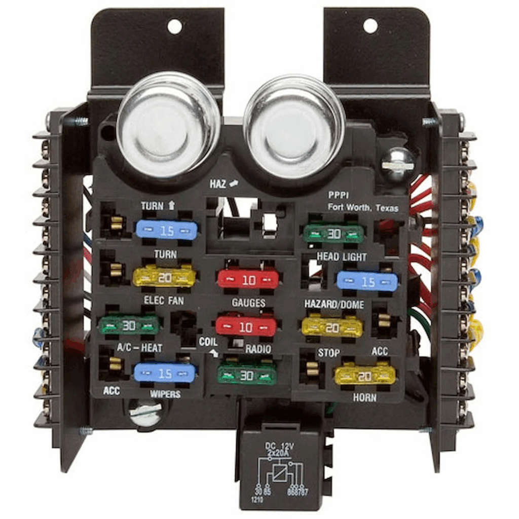
The fuse block is the heart of the wiring harness. It should be mounted in a dry, accessible location.
Common locations include under the dashboard, inside the glove box area, or on the firewall inside the cabin.
Ensure there is enough clearance to access fuses and that wiring can exit cleanly without sharp bends.
Good grounds are just as important as good power feeds.
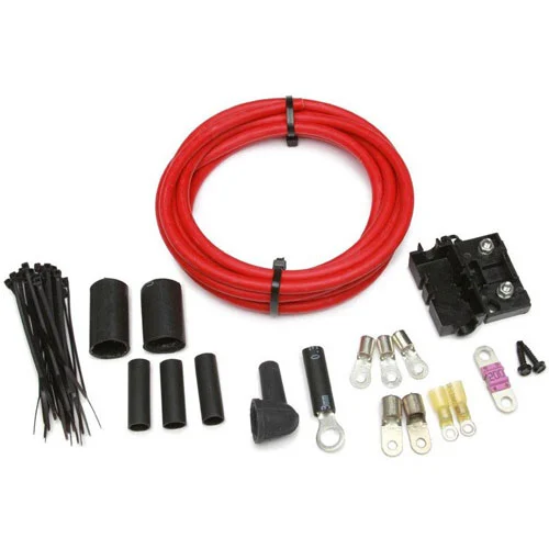
Connect the main power feed according to harness instructions, usually directly to the battery or starter solenoid.
Ground connections should be made to clean, bare metal. Use star washers or dedicated ground straps to ensure solid contact.
Poor grounding is one of the leading causes of electrical problems.
Route the main harness branches to their general areas before making final connections.
Common sections include:
Use grommets when passing through metal panels and secure wiring away from heat sources and moving parts.

Sign up now to join the JEGS email newsletter and be the first to learn about new products, special deals and e-mail only offers!
Connect circuits for ignition, starter, alternator, and engine sensors.
Follow the wiring diagram closely and confirm correct wire gauge and routing. These circuits handle critical functions and higher current loads.
Double check polarity and connections before proceeding.
Lighting circuits are usually straightforward but require careful routing.
Connect headlights, tail lights, brake lights, turn signals, and marker lights as specified. Verify proper grounds at each lighting point.
Test lighting circuits before finalizing connections to catch issues early.
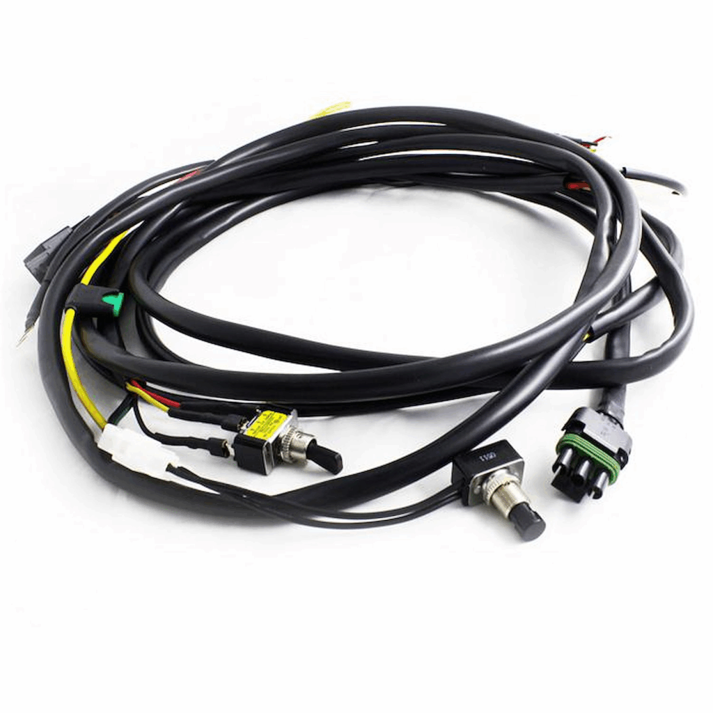
Interior circuits include gauges, dash lighting, heater controls, radio, and power accessories.
Labeling wires as you work helps keep everything organized. Many modern harnesses include printed wire labels, which simplifies this step.
Install switches and accessories according to manufacturer instructions.
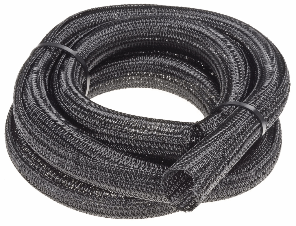
Once all circuits are connected, secure wiring using clamps, loom, or zip ties.
Avoid letting wiring hang loose or rest against sharp edges. Proper protection prevents wear and electrical shorts over time.
Clean routing also improves the overall appearance of the install.
Before reconnecting the battery, visually inspect every connection.
Reconnect the battery and test systems one at a time:
Use a multimeter or test light to verify voltage where needed.
Address any issues before driving the vehicle.
Avoiding common mistakes improves success.
Common issues include:
Taking your time prevents these problems.
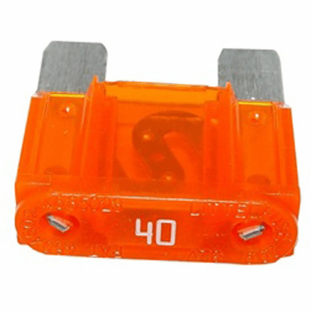
A properly installed wiring harness makes future upgrades easier.
Extra circuits allow for additions like electric fans, fuel pumps, or audio upgrades without redoing the entire system.
Keeping wiring organized pays dividends later.
JEGS carries a wide selection of wiring harnesses, fuse blocks, relays, connectors, and electrical accessories for classic cars, muscle cars, and custom builds.
With trusted brands and complete system solutions, JEGS helps ensure your electrical system is built right from the start.
Wiring harness installation may seem intimidating, but a methodical approach makes it manageable. Planning, careful routing, solid grounding, and thorough testing are the keys to success.
By installing your wiring harness correctly, you create a reliable electrical foundation that supports performance, safety, and long term enjoyment.
Explore wiring harnesses and electrical components at www.jegs.com and take the guesswork out of your next wiring project.
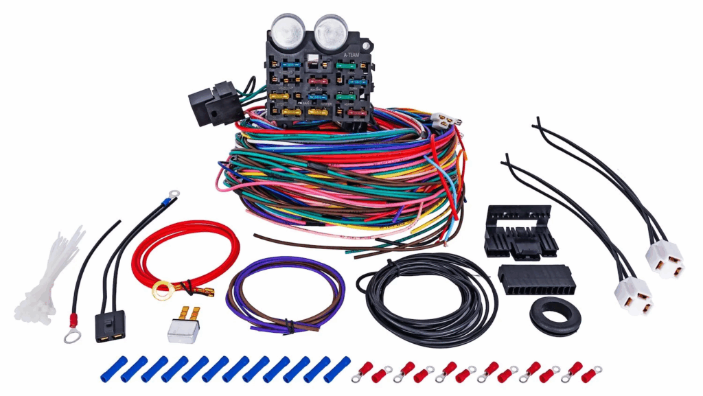

Hey there , I bought a 14 circuit wiring harness from Jegs quite awhile ago and having a hard time getting the turn signals to work with the flashers. It’s for a 1969 Dart and the instructions for the flasher power goes into a GM switch ? #52 purple wire. Just want my blinkers and hazards working I have running lights , brake lights any help would be great thanks Janin

Janin, you’re very close, this is a common hang-up when wiring classic turn signals into a universal harness. The key thing to understand is that the turn signal switch routes power from the flasher to either the left or right side, and also ties into the brake light circuit for the rear lights.
On most 14 circuit harnesses, the flasher power wire going to the column is correct like you described, but you also need to make sure a few other pieces are in place. First, confirm you have power going into the flasher itself, not just out of it. One side of the flasher should have a constant or ignition-fed 12V source depending on the circuit, and the other side feeds the turn signal switch.
Next, the column wiring has to be matched correctly. The GM style column typically uses separate wires for left rear, right rear, left front, and right front turn signals, along with a brake light feed. If the brake light wire is not tied into the switch correctly, the rear signals and hazards will not function properly even if the front ones do.
Also check your grounds. The front signal housings and rear tail lights must be properly grounded to the body. A weak or missing ground will stop the circuit from completing and make it seem like the switch or flasher is not working.
For hazards, make sure you are using the second flasher if your harness has one. Turn signals and hazards usually use separate flashers, and both need power.
Since you mentioned the purple wire going to a GM switch, double check that the rest of the column wires are pinned correctly for that switch style. GM color codes are fairly standard, but they still need to match the harness outputs exactly.
At this point it sounds like a routing or power feed issue more than a bad part. If you want to walk through your exact wire colors and setup step by step, give us a call at 1-800-345-4545 and a Tech Specialist can help you sort it out quickly.





Leave a Reply