

Sign up now to join the JEGS email newsletter and be the first to learn about new products, special deals and e-mail only offers!

 96 People Found This Article Helpful
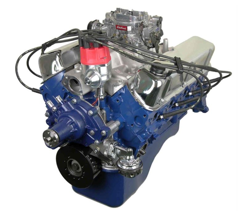

The firing order is the secret behind the heartbeat of every engine. Yet, even seasoned gearheads fail to understand its mechanics, so we bring you this guide. Whether you're an automotive enthusiast or a curious driver looking to understand your vehicle better, this article will tell you everything you want to know about this basic yet often misunderstood topic.
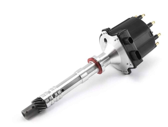
As the name suggests, firing order is the ignition sequence of cylinders in internal combustion engines. It dictates the power delivery sequence and ensures that the combustion of fuel takes place at very exact time periods in each of the cylinders against the rotating assembly, pushing down on the crankshaft via the pistons and connecting rods and ultimately sending power to the wheels. Think of the rotating assembly of an engine like your legs and feet pushing down on the two pedals on a bicycle. If you don't push down on each pedal at the right time, you will not reach maximum power and speed. You'll also get tired more quickly.
The firing order sequence is very important. For example, a typical inline four-cylinder has a 1-3-4-2 firing sequence, and a typical Chevy firing order for a V6 is 1-6-5-4-3-2. The goal is to produce the maximum amount of power without side effects, such as knocking or accelerated crankshaft wear.

It might seem more convenient to make engines with a simple 1-2-3-4-5-6 (and so on) sequence, but this firing order is less than subpar. This is because it would produce uneven twisting forces on the crankshaft and could damage it or entirely destroy it.
The crankshaft is one of the most stressed engine components and performs roughly between 500 and 7,000 rotations per minute based on the specific engine and its rev range. This means the crankshaft could be easily bent if the torsional forces weren’t distributed evenly across the length of it. The firing order largely affects the force distribution and has to factor into the crankshaft design.
The firing phase is physically the strongest of the entire four-stroke cycle, creating vibrations and overall mechanical stress. To maintain engine reliability, the mechanical stress should be kept at the lowest possible level, so firing should not occur at any adjacent cylinders at the same time, this is one of the reasons why engines need a specific firing order.
The firing sequence also affects the engine’s level of vibrations, noise, and generated power, including the evenness of power delivery across the RPM range. An improper firing order can then also negatively impact fuel economy.
In a more literal sense, we need to know the firing order of an engine to not mix up the spark plug wires, which could cause the engine to run poorly and backfire, if it would start at all.

Sign up now to join the JEGS email newsletter and be the first to learn about new products, special deals and e-mail only offers!
To minimize vibrations, most engines are designed to fire in evenly spaced intervals. In other words, the power stroke (i.e., the stage of the engine combustion cycle in which the gasses expand and drive the piston outward) is spaced out evenly between each one of the cylinders. As a result, a six-cylinder will fire at 120-degree intervals. The reason is that a four-stroke engine has a 720 degrees operating cycle. Divide this by the number of cylinders and we get the 120 degrees mentioned above.
Nonetheless, there are exceptions, with certain V6 engines using uneven intervals, such as 90 and 150 degrees. Because this hinders the smoothness of the engine, such intervals are only used on performance engines, where this tradeoff is acceptable, such as the V10-powered Dodge Viper. Another example would be the 5.2 V10 FSI found in Lamborghini and Audi models. The Audi is actually the exception that proves the rule; besides the R8, the unevenly firing V10 also found its way to the luxury sedan S8.

Each engine has a specific firing order, which varies not only based on the number of cylinders but also the manufacturer and general engine design. For example, the 6-cylinder GM 3800 engine has a 1-6-5-4-3-2 sequence, while a 6-cylinder from Mercedes (M104) has a 1-4-2-5-3-6 sequence. Similarly, a Chevy firing order may be different from a firing order for Ford. Moreover, firing sequences can also vary within the manufacturer’s lineup (i.e., the 6-cylinder Mercedes M272 has a different firing order from the 6-cylinder M104).
Below is a list of American V8 firing orders for some select engines. Keep in mind that the table is non-exhaustive and there are many more engine configurations and different firing orders.
| Engine | Firing Order | Distributor Rotation | |
|---|---|---|---|
| AMC V8 Engines | 1-8-4-3-6-5-7-2 | Clockwise | |
| Buick 350 V8 Engines | 1-8-4-3-6-5-7-2 | Clockwise | |
| Cadillac V8 Engines (368/425/472/500) | 1-5-6-3-4-2-7-8 | Clockwise | |
| Cadillac 429 V8 Engine | 1-8-7-2-6-5-4-3 | Clockwise | |
| Cadillac 250 / 4.1L & 273 / 4.5L Engine | 1-8-4-3-6-5-7-2 | Counter-Clockwise | |
| Chevy Small / Big Block V8 Engines | 1-8-4-3-6-5-7-2 | Clockwise | |
| Chrysler Big Block B/RB/Hemi V8 Engines (361/383/400/413/426/440) | 1-8-4-3-6-5-7-2 | Counter-Clockwise | |
| Chrysler/Plymouth Small Block A V8 Engines (273/277/301/303/313/318/326/340/360) | 1-8-4-3-6-5-7-2 | Clockwise | |
| Ford Small Block V8 Engines (up to 1984 year) | 1-5-4-2-6-3-7-8 | Counter-Clockwise | |
| Ford 5.0 H.O. / 351W (Windsor) / 351C (Cleveland) 351M (Modified) / 400 V8 Engines | 1-3-7-2-6-5-4-8 | Counter-Clockwise | |
| Ford FE V8 Engines (352/360/390/406/427/428) | 1-5-4-2-6-3-7-8 | Counter-Clockwise | |
| Ford Big Block V8 Engines (429/460/514) | 1-5-4-2-6-3-7-8 | Counter-Clockwise | |
| Ford Modular 4.6L / 5.4L V8 Engines | 1-3-7-2-6-5-4-8 | Distributorless | |
| Ford Coyote V8 5.0 Engines | 1-5-4-8-6-3-7-2 | Distributorless | |
| GM 8100 8.1L Big Block Chevy Engines | 1-8-7-2-6-5-4-3 | Distributorless | |
| GM Gen III LS V8 Engines (4.8/5.3/5.7/6.0) | 1-8-7-2-6-5-4-3 | Distributorless | |
| GM Gen IV LS V8 Engines (4.8/6.0/6.2/7.0) | 1-8-4-3-6-5-7-2 | Distributorless | |
| GM Gen V LT V8 Engines (5.3/6.2/6.6) | 1-8-7-2-6-5-4-3 | Distributorless | |
| Lincoln V8 Engines (1952-1976) | 1-5-4-8-6-3-7-2 | Counter-Clockwise | |
| Mopar Gen III Hemi V8 Engines (4.7/5.7/6.1/6.2/6.4) | 1-8-4-3-6-5-7-2 | Distributorless | |
| Oldsmobile V8 Engines (260/307/330/350/400/403/425/455) | 1-8-4-3-6-5-7-2 | Counter-Clockwise | |
| Pontiac V8 Engines (265/301/350/400/455) | 1-8-4-3-6-5-7-2 | Counter-Clockwise |
Also, note that flat engines use a different numbering system. “L” stands for the left bank and “R” for the right bank of cylinders. “L1” is thus a designation of the front cylinder on the left bank, “R3” the third cylinder on the right bank, and so on.
Crucial to describing the firing order is also the actual numbering of the cylinders. This largely depends on the engine design and the manufacturer. Cylinders in straight engines are in all cases simply numbered from the front to rear. The second most common engine design is the “V” engine. Here, two approaches are possible. Producers such as Ford and Audi number the cylinders sequentially on each bank. The firing order for Ford engines (when viewed from the front of the engine) would then be 1-2-3-4 for the cylinders along the left bank and 5-6-7-8 for cylinders along the right bank. On the other hand, GM and Chrysler tend to number cylinders relative to their position on the crankshaft instead. In that case, cylinders(when viewed from the front of the engine) along the left bank would be 2-4-6-8 and 1-3-5-7 along the right one.
Closely related to the firing order, and just as important to understand, is what we call companion cylinders. To put this into an example, let’s take the 1-8-4-3-6-5-7-2 firing order, which is common on small and big block Chevys. From this Chevy firing order, we can read that the companion cylinders are 1/6, 8/5, 4/7, and 3/2. Each pair of these cylinders is at the top dead center at the same time (although each is in a different stroke phase). This is determined by the crankshaft throw. The throw is measured as the distance between the center of the crankshaft pin and the crank’s main journal. In other words, the engine firing order depends on the design of the crankshaft. So, by using a different crankshaft, we can alter the firing order.
This is in fact why engine tuners swap crankshafts - altering the firing order can generate a bit extra horsepower (although it usually negatively affects reliability). Specifically, in the case of the Chevy engine above, the firing order of cylinders 4 and 7 is swapped, and also of 3 and 2. As a result, you get a 1-8-7-2-6-5-4-3 firing order, which is identical to LS engines.


The firing order of a 3 or 6 cyl looks like a y with respect to ignition. But hen how does the drop back to the square look on the balanced image for the 4 cyl on the same crank occur? How is that firing order established.going from y to square an back? I cannot picture the firing order that actually occur looking at the end f the crank shaft!

Ned,
That is a really good question and it trips up a lot of people because firing order diagrams are usually drawn in simplified shapes instead of showing what is physically happening at the crankshaft. The key thing to remember is that firing order is not determined by a shape at the end of the crank, it is determined by crank pin placement, piston pairing, and when each cylinder reaches top dead center on the compression stroke. On a three or six cylinder engine, the crank pins are spaced 120 degrees apart, which is why ignition events are evenly spaced every 120 degrees of crank rotation and often get drawn like a Y. A straight six is basically two mirrored three cylinder groups sharing the same evenly spaced crank geometry, so the firing stays smooth and evenly timed. A four cylinder is different because the crank has only two crank pins, spaced 180 degrees apart, and the pistons are paired. Cylinders 1 and 4 move together, and cylinders 2 and 3 move together. When one pair is at top dead center, the other pair is at bottom dead center. Even though two pistons reach the top at the same time, only one of them is on the compression stroke and ready to fire. The other is finishing exhaust. That is why a four cylinder fires every 180 degrees of crank rotation, even though the pistons move in pairs. There is no actual drop from a Y to a square mechanically. The square you often see in diagrams is just a way to visualize even firing intervals, not the physical crank layout. If you were looking at the end of the crankshaft, you would only see two opposing throws, not four separate positions. The camshaft timing and valve events are what decide which cylinder fires when both pistons are at the top. That is how the firing order is established and why a four cylinder can still be evenly balanced even though the crank looks much simpler than a six. If you want to talk through this with diagrams or look at specific engine layouts, give our tech team a call at 1-800-345-4545 and they will be happy to walk you through it.

Thank you for that if I get it running soon I would love to see and hear it running
that’s very nice thank you
528 Hemi firing order 18436572 I am not convinced that there could be collision between the valves and a piston I am just afraid, you see there is a guy out there he starts out all good except when #8 is at TDC there is no valves opening up and no cylinder heads on
Hi JV,
Your concern is valid, and it’s smart to double-check before buttoning up an engine like your 528 Hemi. The firing order for the 426-based Hemi and its stroked versions like the 528 is indeed 1-8-4-3-6-5-7-2, just like other Mopar big blocks.
If you’re checking TDC on cylinder #8 and there are no cylinder heads installed, you’re only seeing piston movement, not valve activity. So it’s perfectly normal for there to be no valves opening at TDC unless you’ve also installed and timed the camshaft and valvetrain. Without the heads and valve train in place, the piston will simply come up to TDC on its own, and it won’t show any valve movement.
Now, if you’re worried about valve-to-piston clearance, that’s usually only a risk with high-lift cams, tight piston-to-valve specs, or mistimed camshafts. Once the cam, timing set, and heads are installed, you’ll want to clay the pistons during a mock-up to physically check that clearance if you’re using aggressive cam specs.
So no worries just yet. What you’re seeing sounds normal for where you’re at in the build. But once you’re ready to assemble the top end, it’s a good idea to verify piston-to-valve clearance before final assembly.
If you need help checking that or want to talk about camshaft timing and safe clearances, give us a call at 1-800-345-4545 and one of our tech specialists will walk you through it. Appreciate you reaching out. That Hemi’s gonna be a beast.





Leave a Reply