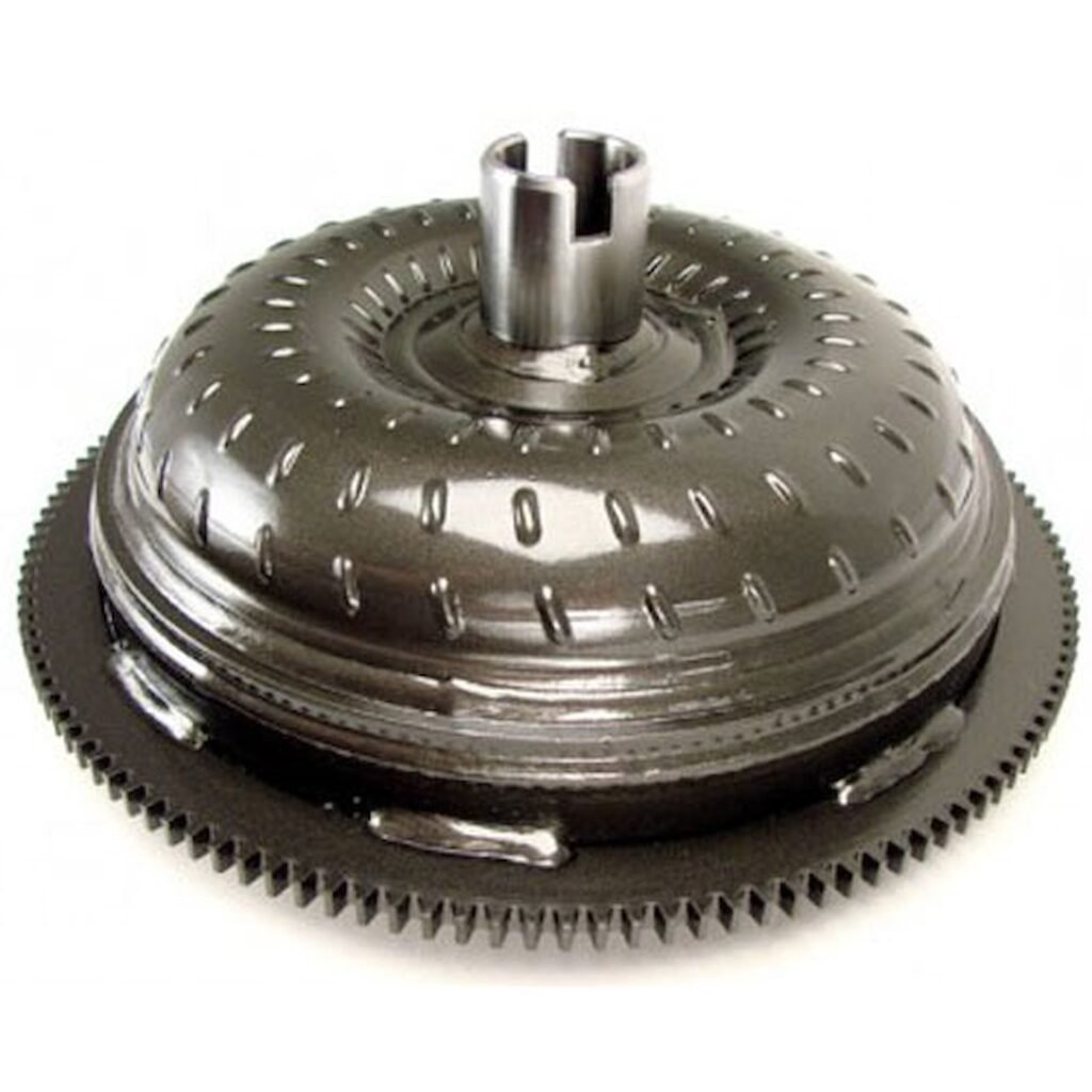
What Does A Torque Converter Do?
A torque converter is a key component in automatic transmissions, serving as a vital link between the engine and the transmission. Its primary function is to transfer power from the engine to the transmission while allowing the engine to continue running even when the vehicle is stationary. This is achieved through a fluid coupling mechanism. Inside the torque converter, there are two main elements: the impeller, which is connected to the engine, and the turbine, which is linked to the transmission input shaft. These elements are immersed in transmission fluid. As the engine rotates the impeller, it generates fluid movement, which in turn causes the turbine to spin, transmitting power to the transmission. Importantly, the design of a torque converter allows for a certain amount of slippage between the impeller and turbine, enabling smooth acceleration and preventing stalling. Additionally, torque converters provide a torque multiplication effect, amplifying the engine torque during initial acceleration, which is particularly beneficial for heavy loads or steep inclines.
How Does A Torque Converter Work?
When the vehicle is in “park” while the engine is running, the converter is spinning but the transmission is locked internally, preventing the transfer of power and movement to the rest of the drivetrain. When shifted into “drive”, the transmission unlocks and allows forward movement of the vehicle under power. However, the converter slips enough for the engine to continue to rotate while the brakes are applied. If the converter did not slip and the brakes were applied, the engine would die, as it could not spin the crankshaft, which would be directly connected from the flexplate to the "locked" (from depressed brake pedal) tires. Once the brake pedal is released, the vehicle begins to move with the converter still slipping some. Once the engine rpms increase, the centrifugal force inside the torque converter causes it to engage the transmission input shaft more and slippage lessens. Once the converter stall speed is reached, the converter is fully engaged (yet still with some slippage) in completely coupling the engine to the transmission. Lock-up converters, typically found in street vehicles with overdrive transmissions, will 100% lock up with no slippage between the engine and transmission. This usually happens once the vehicle is in the highest gear and at a steady speed at highway speeds, with the vehicle ECU applying electrical power to the lock-up solenoid. The additional reduction in converter slippage lowers the engine rpms and helps the transmission to stay cooler as friction and slippage cause heat, lowering transmission life. This also improves engine fuel economy and longevity.
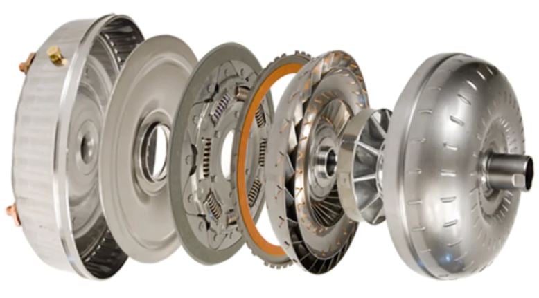
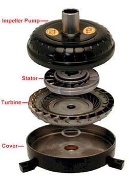
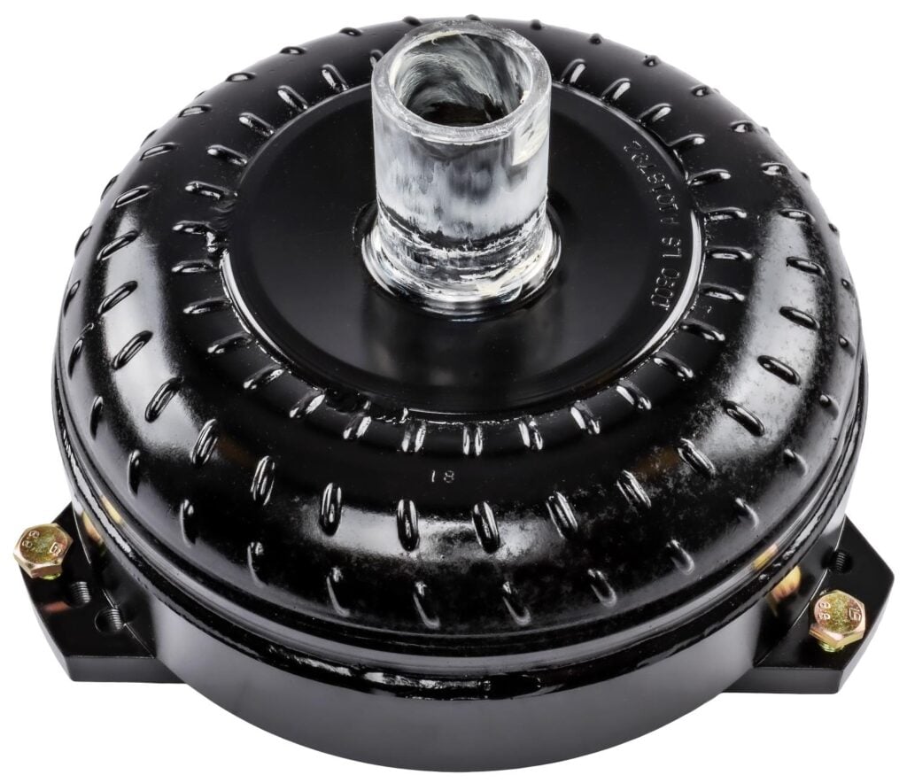
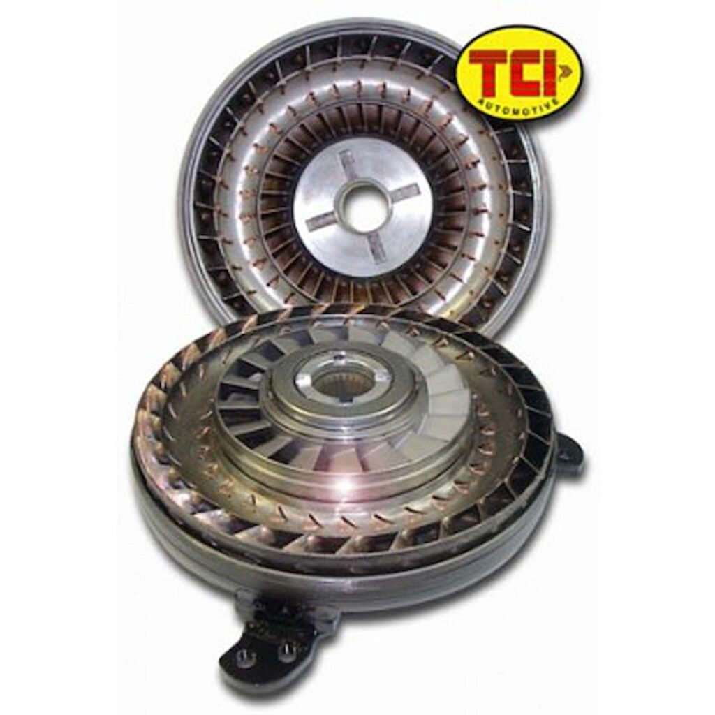
The Torque Converter Consists Of Four Primary Components:
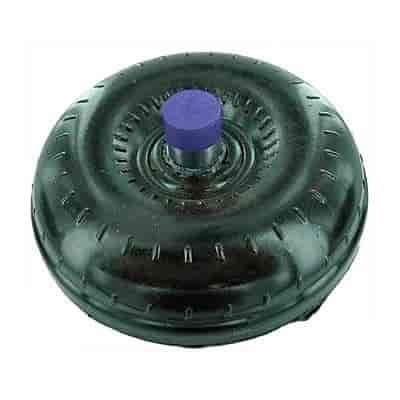
Cover --- the cover (also referred to as a front) is the outside half of the housing toward the engine side from the weld line. The cover serves to attach the converter to the flexplate (not flywheel, which is for manual transmissions/clutches) via flexplate bolts and contains the transmission fluid. While the torque converter cover is not actively involved in the characteristics of the performance, it is important that the cover remain rigid under stress (torsional and thrust stress and the tremendous hydraulic pressure generated by the torque converter internally.)
Turbine --- the converter turbine rides within the cover and is attached to the drivetrain via a spline fit to the input shaft of the transmission. When the turbine moves, the car moves.
Stator --- the stator can be described as the "brain" of the torque converter, although the stator is by no means the sole determiner of converter function and characteristics. The stator, which changes fluid flow between the turbine and pump, is what makes a torque converter a torque converter (multiplier) and not strictly a fluid coupler.
With the stator removed, however, it will retain none of its torque multiplying effect. In order for the stator to function properly the sprag must work as designed: (1) It must hold the stator perfectly still (locked in place) while the converter is still in stall mode (slow relative turbine speed to the impeller pump speed) and (2) allow the stator to spin with the rest of the converter after the turbine speed approaches the pump speed. This allows for more efficient and less restrictive fluid flow.
Sprag --- The sprag is a one-way mechanical clutch mounted on races and fits inside the stator while the inner race splines onto the stator support of the transmission. The torque multiplier effect means that a vehicle equipped with an automatic transmission and torque converter will output more torque to the drive wheels than the engine is actually producing. This occurs while the converter is in its "stall mode" (when the turbine is spinning considerably slower than the pump) and during vehicle acceleration. Torque multiplication rapidly decreases until it reaches a ratio of 1:1 (no torque increase over crankshaft torque.) A typical torque converter will have a torque multiplication ratio in the area of 2.5:1. The main point to remember is that all properly functioning torque converters do indeed multiply torque during initial acceleration. The more drastic the change in fluid path caused by the stator from its "natural" return path, the higher the torque multiplication ratio a given converter will have. Torque multiplication does not occur with a manual transmission clutch and pressure plate; hence the need for heavy flywheels, very high numerical gear ratios, and high launch rpm. A more detailed discussion of torque multiplication can get very confusing to the layman as high multiplication ratios can be easily considered the best choice when in fact more variables must be included in the decision. Remember, the ratio is still a factor of the engine torque in the relevant range of the torque converter stall speed, i.e.: a converter with a multiplication ratio of 2.5:1 that stalls 3000 rpm will produce 500 ft.-lbs. of torque at the instance of full throttle acceleration if its coupled to an engine producing 200 ft.-lbs. of torque at 3000 rpm. However, if this same engine produces 300 ft.-lbs. of torque at 4000 rpm, we would be better off with a converter that stalled 4000 rpm with only a 2.0:1 torque multiplication ratio, i.e.: 300 x 2.0 = 600 ft.-lbs. at initial acceleration. Of course it would be better yet to have a 2.5:1 ratio with the 4000 rpm in this example (provided his combination still allows the suspension to work and the tires don't spin.) This is just a brief overview as the actual scenarios are endless.
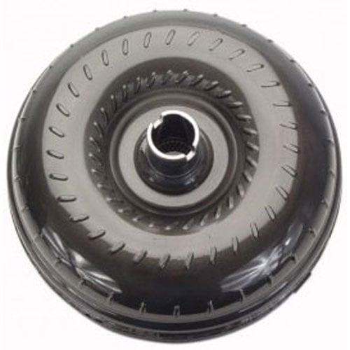
Impeller pump --- the impeller pump is the outside half of the converter on the transmission side of the weld line. Inside the impeller pump is a series of longitudinal fins, which, drive the fluid around its outside diameter into the turbine, since this component is welded to the cover, which is bolted to the flywheel. The size of the torque converter (and pump) and the number and shape of the fins all affect the characteristics of the converter. If long torque converter life is an objective, it is extremely important that the fins of the impeller pump are adequately reinforced against fatigue and the outside housing does not distort under stress.
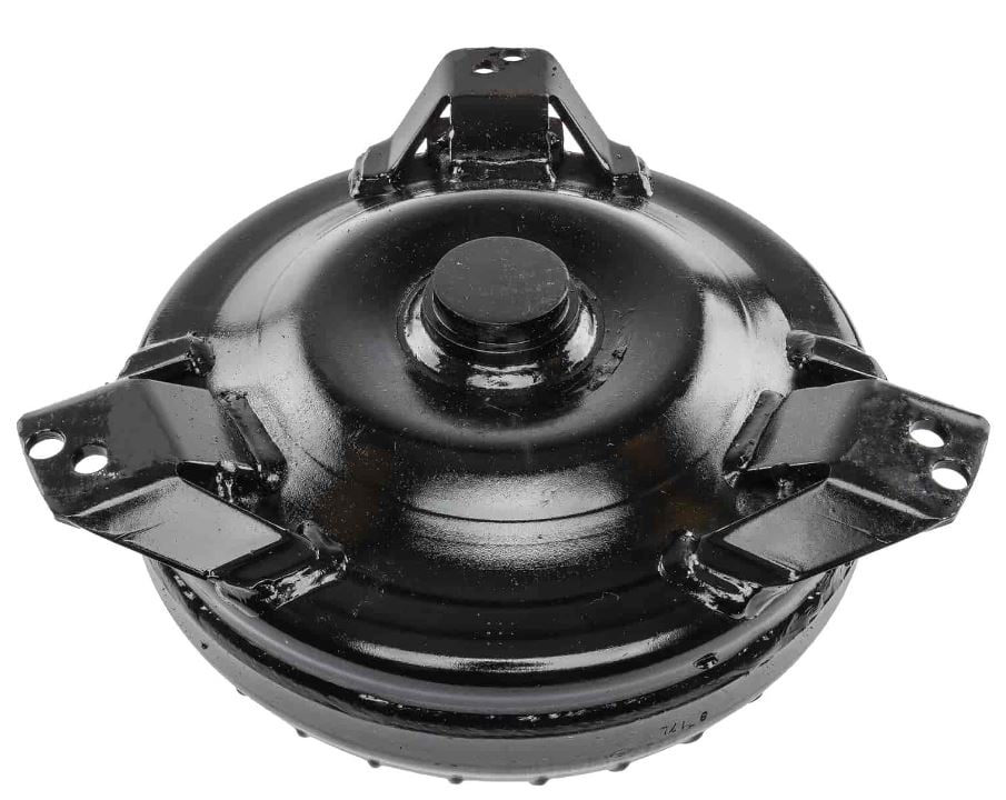
Where Is The Torque Converter Located?
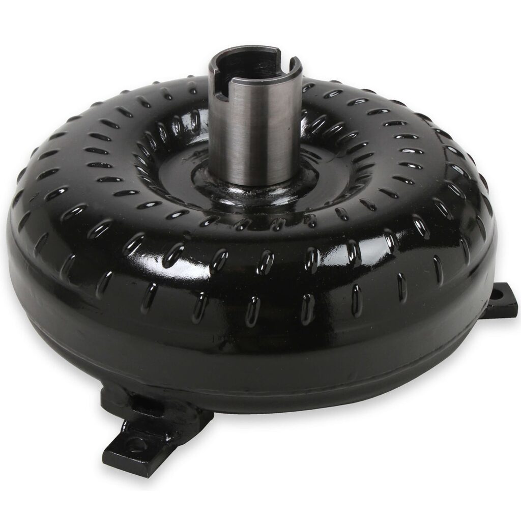
The torque converter is located inside the transmission bellhousing between the engine and transmission. It is bolted to the flexplate, which is fastened to the engine crankshaft on one end. On the other side, it slides onto the splined transmission input shaft. It is protected with a dust cover (sometimes missing) typically mounted at the bottom between the engine and transmission to prevent debris from being caught in the spinning operation.
How Much Is A Torque Converter?
Torque converters can range anywhere from under $200 for a stock replacement, to thousands of dollars for an all-out race converter, which is capable of handling nitrous, supercharged, and turbocharged 1000+ horsepower engines.
What Torque Converter Do I Need?
Selecting the proper torque converter for your automatic transmission application is one of the most important decisions to make for your vehicle’s drivetrain. When selecting a torque converter there are several factors involved.
The first is the transmission type, as the torque converter needs to match the transmission. This includes the input shaft spline count, whether the transmission is a “lock-up” style or “non-lock-up” style, as well as matching the transmission configuration (for example, some Ford transmissions have “case-fill” and “pan-fill” designs requiring a different converter physical size for clearance).
The torque converter also needs to match the flexplate diameter and bolt pattern.
The next step is matching the converter to the engine’s horsepower. All aftermarket converters have a maximum horsepower rating that it has been tested to be able to handle.
Next is the anti-ballooning plate option. An anti-ballooning plate is used for applications with nitrous, turbocharged, or supercharged engines as well as transmissions equipped with a transbrake. This plate provides additional strength to the converter from the sudden increase in power created from power adders and hard launches, reducing the chances of an explosion and complete converter failure.
Finally, the correct stall speed needs selected to properly match the engine's camshaft as well as vehicle weight, tire diameter and final drive gear ratio. Too low of a stall speed and the engine will stall or have a boggy take-off. Too high of stall and loss of power will result under the stall speed as well as unnecessary heat created in the transmission. JEGS offers a wide selection of torque converters to choose from to meet your vehicle needs.
What Stall Converter Do I Need?
The general rule is to select a converter stall speed that is 400-500 rpms above the beginning of the engine camshaft’s power band. For example, if the camshaft you purchased for your engine has a power band of 2000-6000 rpms, the converter should have around 2400-2500 rpm of stall. To get an even more accurate stall speed additional engine and vehicle information is needed. For example, a big block engine tends to stall higher than a small block engine. A heavier car also will cause the converter to stall higher than a lightweight vehicle. The rear tire diameter and gear ratio also affect stall speed. A numerically higher gear ratio will cause the converter to stall less, as the vehicle takes off easier than with a numerically lower gear ratio. The same applies with a taller (causing higher stall speeds) vs smaller tires (resulting in lower stall speeds). Most converters have a stall speed range that is advertised with anywhere from 200 - 400 of rpms (for example, "2200-2400 stall"). Taking into account weight, gear ratio, and tire size will help you to determine where in that range the actual stall speed will be for your specific vehicle. If using the converter on a street vehicle that will see highway use, you need to confirm that the stall speed is below your cruising rpm. If the vehicle is cruising at 65 mph in the highest transmission gear and the engine rpms are under the stall speed, the converter is still slipping. This generates a lot of heat and wear on the converter as well as the transmission. It will also cause a slipping behavior until the engine rpm matches the stall speed. If the correct stall speed has already been confirmed, changing the rear tire diameter (using a smaller tire) or gear ratio (using a numerically higher ratio) will help to raise the rpms above the stall speed and avoid transmission component damage.
Per TCI Transmissions, "Stall speed refers to the rpm that a given torque converter (impeller) has to spin in order for it to overcome a given amount of load and begin moving the turbine. This means how fast (rpm) the torque converter must spin to generate enough fluid force on the turbine to overcome the resting inertia of the vehicle at wide open throttle. Load originates from two places. The first is from the torque imparted on the torque converter by the engine via the crankshaft. (This load varies over rpm, i.e. torque curve, and is directly affected by atmosphere, fuel and engine conditions.) The second is from inertia, the resistance of the vehicle to acceleration, which places a load on the torque converter through the drive train. This can be thought of as how difficult the drivetrain is to rotate with the vehicle at rest, and is affected by car weight, amount of gear reduction and tire size, ability of tire to stay adhered to ground, and stiffness of chassis.
While referring to the resistance of the vehicle to move while at rest, the torque converter's stall speed and much of its characteristics for a given application are also affected by the vehicle's resistance to accelerate relative to its rate of acceleration. This resistance has much to do with the rpm observed immediately after the vehicle starts moving, the amount of rpm drop observed during a gear change, and the amount of slippage in the torque converter (turbine rpm relative to impeller pump rpm.) A discussion involving how resistance to acceleration affects a torque converter involves more theory than fact and must involve all the dozens of other variables that affect rpm and slippage. The primary thing to remember about torque converter stall speed is that a particular torque converter does not have a "preset from the factory" stall speed but rather its unique design will produce a certain range of stall speeds depending on the amount of load the torque converter is exposed to. This load comes from both the torque produced by the engine and the resistance of the vehicle to move from rest. The higher this combined load the higher stall we will observe from a particular torque converter, and conversely, the lower the load, the lower the stall speed. Naturally, if the engine is not at wide open throttle we will not expect to observe as high a stall speed as we would under a wide open throttle.
Another point concerning engine torque is that we are only focusing on what we'll call the "relevant range" of the engine torque curve when discussing initial stall speed. This means if a particular torque converter chosen has a design that should produce a stall speed in a range of say 2000 to 2600 rpm given the application then we would refer to this as the relevant range of interest in the engine's torque curve for this particular torque converter. In other words, only the torque characteristics of the engine in this rpm range will affect the amount of stall speed we actually observe. If we are using a high horsepower / rpm engine that does not make much torque before 3000 rpm, it does not matter that the engine makes excellent torque over 3000 rpm if we are trying to use the torque converter in this example because its relevant range is 2000-2600 rpm and we would expect to see poor stall (2000 rpm or less) due to the poor torque produced by the engine in this range.
Too Low Of Stall Speed
If an application requires at least 3000 rpm stall and a 2000 to 2500 rpm stall range converter is used, it will normally not even provide the 2000 rpm stall. It will act very similar to the stock torque converter that was just removed. Why? Because the engine needs to operate in its optimum rpm range and since the chosen torque converter is below that range, it is not getting enough load from the crankshaft side to operate as designed. Symptoms include engine stalling when in gear at a stop, low stall speed, hesitation when going to full throttle, a "bog" when leaving from stop at wide open throttle.
Too High Of Stall Speed
This happens most often when there is not sufficient gear ratio for the converter stall range or the engine is not capable of the appropriate rpm range (too small a duration camshaft, inadequate valve springs, too low compression, etc.) Symptoms include high "revs" to pull away from stop, "marshmallow" accelerator feel when driving at part throttle, transmission and possibly engine overheating, and a pronounced engine rev when nailing the throttle from a cruising speed."
What Is The Difference In The Terms "Flash Stall" And "Foot-Brake Stall"?
Of the two measurements of torque converter stall, 'Flash Stall' is the most accurate. Foot-Brake stall is dependent upon too many variables. (i.e. type of braking system, disc or drum brakes, how well adjusted the brake system is, ring and pinion ratios affect foot-brake stall more dramatically, idle characteristics of the engine, cam installation for low-end torque as needed by an automatic transmission.)
Flash Stall can be determined a couple of different ways:
-With the vehicle sitting still and idling in low gear, apply full throttle. As the vehicle begins its motion forward, notice the RPM hand on the tachometer. That is your Flash Stall. (Engine should be very responsive from idle. If not, camshaft timing and/or carburetor adjustments may need to be made in order for the engine to be crisp from idle.)
-With the vehicle in forward motion in high or drive gear and at its lowest mph where it will not kick back to a lower gear, apply full throttle while noticing the rpm hand of the tachometer. (This measurement of a flash stall is best achieved with a full manual(shift) race auto transmission.)
How To Tell If A Torque Converter Is Bad
The torque converter manufacturer should always be consulted first for the proper steps and recommendations on testing a torque converter in the vehicle. However, a simple test can be performed to determine if it is working properly. The testing method is not compatible with vehicles equipped with traction control, anti-lock brake systems, or computer-controlled transmissions. Great care must be taken so that damage does not result to any vehicle components. First, all engine, transmission, and vehicle fluids must be in good condition and at the proper level. The vehicle needs to have the parking brake set and with the tires chocked to prevent any possibility of vehicle movement. A tachometer is required and must be clearly seen from the driver seat. Next, press the brake pedal all the way down and start the engine in park. Then shift the transmission into drive while still holding the brakes at the same pressure to prevent vehicle movement. With one foot on the brake pedal and the other to be used on the accelerator pedal, and while watching the tachometer rpms, press the accelerator all the way down between 2-3 seconds, but not exceeding 4 seconds as damage may result to the transmission. The stall speed of the converter is the maximum rpm the engine revved up to during that 2-3 second interval. If the stall speed does not match the manufacturer’s specified stall range, the converter and/or transmission need further inspection to confirm what component(s) are not working properly or which parts are damaged.
What Does The Term "Lock-Up" Torque Converter Mean?
This term refers to a converter that contains an internal lock-up piston or device, either friction or mechanical. Transmissions such as TH350C, 2004R, 4L60 (700R4), 4L60E, 4L80E, AOD, AODE/4R70W, and others, use these methods of eliminating slippage for an increase in fuel economy. Older transmissions such as the TH400, TH350, C6, C4, and others did not incorporate these methods of lock-up. The only way to increase fuel efficiency in these types of converters is to change clearances, redirect fin angles, and usually lower the actual stall speed. Locking up the torque converter results in lowering engine rpms as well as transmission fluid temperature.
How To Replace A Torque Converter Clutch Solenoid
Depending on the transmission type, the steps required to replace a torque converter clutch solenoid on lock-up transmissions will be different. Most solenoids are located near the valve body and the front of the transmission. In many applications, replacement can be performed by removing the transmission fluid pan. Locating the transmission shop manual for your application will provide the correct instructions on proper replacement.
Should I Replace The Front Seal And Bushing In My Transmission Before Installing A New Torque Converter I Just Purchased?
Yes. You should inspect the old torque converter you are removing for damage to the converter hub that rides in the pump of the transmission. If you find any wear on the hub at all, you should replace both seal and bushing. If you find no wear at all, you may be fine with just a seal replacement. You should at least do one (seal) if not both (seal & bushing).
What Type Of Clearance Should I Have Between The Torque Converter And Flexplate Before Moving The Converter Forward And Bolting It To The Flexplate?
You should have 1/8" (.125") to 3/16" (.1875") between the torque converter and flexplate before pulling the converter forward front the transmission and bolting it to flexplate.
Can't Find The Torque Converter You Are Looking For?
A JEGS expert is ready to answer your questions and help you find the torque converter that you require for your specific application.